Embed Size (px)
Citation preview
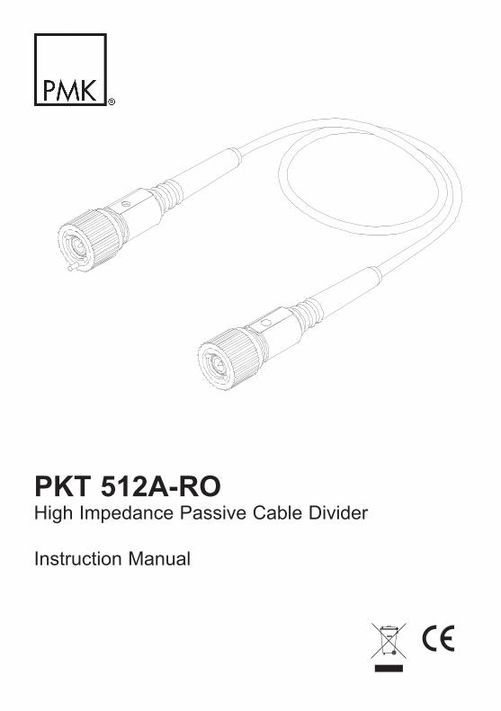
PKT 512A-ROHigh Impedance Passive Cable Divider
Instruction Manual
2
Copyright © 2011 PMK GmbH All rights reserved.
Information in this publication supersedes that in all previously published material.Specifications are subject to change without notice.
Manufacturer
PMK Mess- und Kommunikationstechnik GmbHKönigsteiner Str. 9865812 Bad Soden, Germany Internet: www.pmk-gmbh.com
Tel: +49 (0) 6196 5927 - 930 E-Mail: [email protected] Fax: +49 (0) 6196 5927 - 939 [email protected]
Warranty
PMK GmbH warrants this oscilloscope accessory for normal use and operation within specifications for a peri-od of two (2) years from date of shipment and will repair or replace any defective product which was not dama-ged by negligence, misuse, improper installation, accident or unauthorized repair or modification by the buyer. This warranty is applicable only to defects due to material or workmanship. PMK GmbH disclaim any other implied warranties of merchantability or fitness for a particular purpose. PMK GmbH will not be liable for any indirect, special, incidental, or consequential damages (including damages for loss of profits, loss of business, loss of use or data, interruption of business and the like), even if PMK GmbH has been advised of the possibility of such damages arising from any defect or error in this manual or product.
3
Declaration of Conformity PKT512A-RO
(EC conformity marking)
The manufacturer declares the conformity of this product with the actual required safety standards in accordance with the Low Voltage Directive (LVD) 2006/95/EC:
CEI/IEC 61010-031:2008 Safety requirements for electrical equipment for measurement, control and laboratory use -
Part 031: Safety requirements for hand-held probe assemblies for electrical measurement and test
WEEE/ RoHS Directives
(EC conformity marking)
This electronic product is classified within the WEEE/ RoHS* category list as monitoring and control equipment (category 9). Category 9 products are exempted from the restrictions under the scope of the RoHS directive.
Your help and efforts are required to protect and keep clean our environment. Therefore return this electronic product at the end of its life either to the manufacturer or take care of separate WEEE collection and professional WEEE treatment yourself. Do not dispose as unsorted municipal waste!
* EC Directives:WEEE Directive 2002/96/EC - Waste Electrical and Electronic EquipmentRoHS Directive 2002/95/EC - Restriction of the use of certain Hazardous Substances in Electrical and Electronic Equipment
4
IEC Measurement Categories PKT512A-RO
Definitions and Examples (Clause 6.5.2)
Measurement Category I Definition: Measurement category I is for measurements performed on circuits not directly connected to a mains supply.
Examples: Measurements in circuits not derived from a mains supply and specially protected ( internal ) circuits derived from a mains supply. In the latter case, transient stresses are variable; for that reason it is required that the transient withstand capability of the equipment is made known to the user.
Measurement Category II Definition: Measurement category II is for measurementsCAT II performed on circuits directly connected to the low voltage installation.
Examples: Household appliances, portable tools and similar equipment.
Measurement Category III Definition: Measurement category III is for measurements CAT III performed in the building installation.
Examples: Measurements on distribution boards, circuit breakers, wiring including cables, bus-bars, junction boxes, switches, socket-outlets in the fixed installation and equipment for industrial use like for example stationary motors with permanent connection to the fixed installation.
Measurement Category IV Definition: Measurement category IV is for measurements CAT IV performed at the source of the low-voltage installation.
Examples: Electricity meters and measurements on primary over current protection devices and and ripple control units.
5
IEC Pollution Degrees PKT512A-RO
Definitions (Clause 3.5.6 )
Pollution Degree 1 No POLLUTION or only dry, non conductive POLLUTION. NOTE The POLLUTION has no influence.
Pollution Degree 2 Only- non conductive POLLUTION. Occasionally, however, a temporary conductivity caused by condensation must be accepted.
Pollution Degree 3 Conductive POLLUTION occurs or dry, non-conductive POLLUTION occurs which becomes conductive due to condensation which is to be expected.
IEC Safety Symbols
The following symbols may appear on the product or in this instruction manual:
Caution, risk of danger. Refer to manual.
Caution, risk of electric shock.
Earth (ground) TERMINAL.
66
Safety Information PKT512A-RO
To avoid personal injury and to prevent fire or damage to this product or products connected to it, review and comply with the following safety precautions. Be aware that if you use this probe assembly in a manner not specified the protection this product provides may be impaired.Only qualified personnel should use this probe assembly.
Use only grounded instruments.Do not connect the probe ground lead to a potential other than earth ground. Always make sure the probe and the measurement instrument are grounded properly.
Connect and disconnect properly.Connect the probe output to the measurement instrument and connect the ground lead to earth ground before connecting the probe to the circuit under test. Disconnect the probe input and the probe ground lead from the circuit under test before disconnecting the probe from the measurement instrument.
Observe probe and probe accessory ratings.Do not apply any electrical potential to the probe input which exceeds the maximum ratings of the probe or the accessories connected to it. In a combination always the lower rating / measurement category applies to both probe and accessories connected to it. Make sure to comply with the voltage versus frequency derating curve on page 8.
Keep away from live circuits.Avoid open circuitry. Do not touch connections or components when power is present.
Do not operate with suspected failures.Refer to qualified service personnel.
Indoor use only.Do not operate in wet/damp environment. Keep product surfaces dry and clean.
77
Handling PKT512A-RO
Note that the probe cable is a sensitive part of the probe. Do not damage through excessive bending or pulling. Avoid mechanical shock to this product in general to
guarantee accurate performance and protection.
Maintenance
Cleaning
To clean the exterior of the probe use a soft cloth moistened with either distillated water or isopropyl alcohol. Before use allow the probe to dry completely.
8
Specifications PKT512A-RO
Specifications that are not defined to be guaranteed are typical and are published as general information to the user. The instrument should have warmed-up for at least 20 minutes and the environmental conditions do not exceed the cable divider´s specified limits.
Electrical Specifications
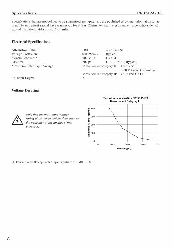
Attenuation Ratio (1) 10:1 ± 2 % at DCVoltage Coefficient 0.0025 %/V (typical)System Bandwidth 500 MHz (-3 dB)Risetime 700 ps (10 % - 90 %) (typical)Maximum Rated Input Voltage Measurement category I: 400 V rms 1250 V transient overvoltage Measurement category II: 300 V rms CAT IIPollution Degree 2
Voltage Derating
Note that the max. input voltage rating of the cable divider decreases as the frequency of the applied signal increases.
(1) Connect to oscilloscope with a input impedance of 1 MΩ ± 1 %.
Typical voltage derating PKT512A-ROMeasurement Category I
0
100
200
300
400
10K 100K 10M 100M 1G
Frequency [Hz]
Am
plitu
de A
C rm
s [V
]Sin
us
9
Specifications PKT512A-RO
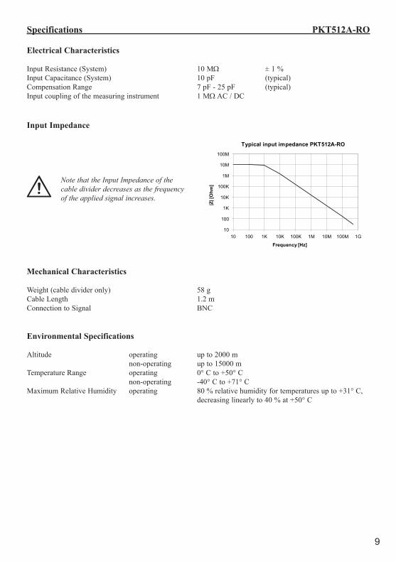
Electrical Characteristics
Input Resistance (System) 10 MΩ ± 1 %Input Capacitance (System) 10 pF (typical)Compensation Range 7 pF - 25 pF (typical)Input coupling of the measuring instrument 1 MΩ AC / DC
Input Impedance
Note that the Input Impedance of the cable divider decreases as the frequency of the applied signal increases.
Mechanical Characteristics
Weight (cable divider only) 58 gCable Length 1.2 mConnection to Signal BNC
Environmental Specifications
Altitude operating up to 2000 m non-operating up to 15000 mTemperature Range operating 0° C to +50° C non-operating -40° C to +71° CMaximum Relative Humidity operating 80 % relative humidity for temperatures up to +31° C, decreasing linearly to 40 % at +50° C
Typical input impedance PKT512A-RO
10
100
1K
10K
100K
1M
10M
100M
10 100 1K 10K 100K 1M 10M 100M 1G
Frequency [Hz]
|Z| [
Ohm
]
10
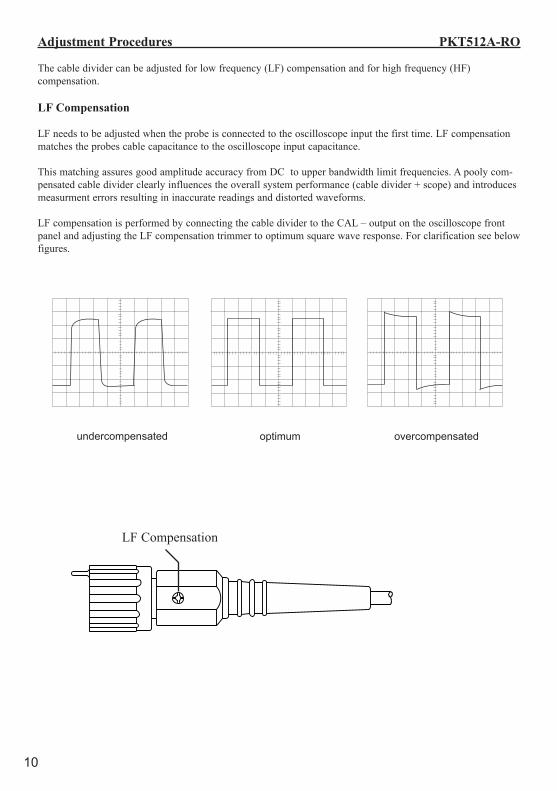
Adjustment Procedures PKT512A-RO
The cable divider can be adjusted for low frequency (LF) compensation and for high frequency (HF) compensation.
LF Compensation
LF needs to be adjusted when the probe is connected to the oscilloscope input the first time. LF compensation matches the probes cable capacitance to the oscilloscope input capacitance.
This matching assures good amplitude accuracy from DC to upper bandwidth limit frequencies. A pooly com-pensated cable divider clearly influences the overall system performance (cable divider + scope) and introduces measurment errors resulting in inaccurate readings and distorted waveforms.
LF compensation is performed by connecting the cable divider to the CAL – output on the oscilloscope front panel and adjusting the LF compensation trimmer to optimum square wave response. For clarification see below figures.
undercompensated optimum overcompensated
LF Compensation
11
Adjustment Procedures PKT512A-RO
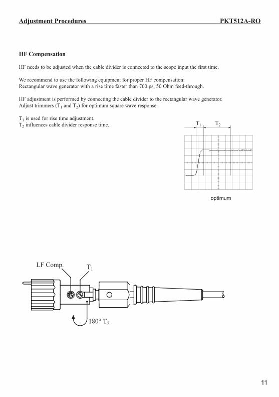
HF Compensation
HF needs to be adjusted when the cable divider is connected to the scope input the first time.
We recommend to use the following equipment for proper HF compensation: Rectangular wave generator with a rise time faster than 700 ps, 50 Ohm feed-through.
HF adjustment is performed by connecting the cable divider to the rectangular wave generator. Adjust trimmers (T1 and T2) for optimum square wave response.
T1 is used for rise time adjustment. T2 influences cable divider response time.
optimum
T1 T2
LF Comp.
180° T2
T1
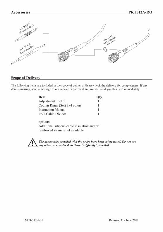
Scope of Delivery
The following items are included in the scope of delivery. Please check the delivery for completeness. If any item is missing, send a message to our service department and we will send you this item immediately.
Item Qty Adjustment Tool T 1 Coding Rings (Set) 3x4 colors 1 Instruction Manual 1 PKT Cable Divider 1 options Additional silicone cable insulation and/or reinforced strain relief available.
The accessories provided with the probe have been safety tested. Do not use any other accessories than those “originally” provided.
M58-512-A01 Revision C - June 2011
890-010-912
Set Codingrings
3x4 Colors
018-292-024
Adjustm
ent Tool
BERNSTE
IN
018-292-007
Adjustm
ent Tool T
Accessories PKT512A-RO