Embed Size (px)
Citation preview

NT86
402
- 201
8 11
ème E
d. pa
g.1/10
I N S T R U M E N T S D E M E S U R E
Centrale de mesuremultifonctions pourréseau basse tension
4 modules
Réseau triphasé 80...500V (phase-phase)Raccordement sur TC dédié
Rapport TC et TT externe programmableEnergie active cl.0,5
Sortie impulsions/alarme/commutation étatCommunication RS485 protocole
ModBus RTU/TCP ou BACNETDiagnostic, correction séquence de phase
Interface externe:Communication Ethernet (NT809 - NT891)
Network monitorfor low voltage4 modules
3-phase line 80...500V (phase-phase)Connection on dedicated CT Programmable external CT and VT ratioActive energy class 0,5 Pulse output/alarm/state switchingRS485 communication byModBus RTU/TCP or BACNET protocolPhase sequence correction, diagnostics
External interfaces:Ethernet communication (NT809 - NT891)
MULTIMESUREMULTIMETERING
Tension par phase et composée Phase and linked voltage
Courant par phase et du neutre Neutral and phase current
Courant moyen et valeur max. du courant moyenCurrent demand and current max. demand
FréquenceFrequency
Facteur de puissancePower factor
Puissance active, réactive, apparenteActive, reactive phase power
Puissance moyenne et valeur max. puissance moyennePower demand and power max. demand
Energie active et réactive, positiveet négative, totale et partielleTotal and partial, positive and negative active and reactive energy
Energie active tarifaire, 4 tarifsTariff active energy, 4 tariff
Heures et minutes de fonctionnementWorking hours and minutes
THDV et THDITHDV and THDI
Analyse des harmoniquesHarmonic analysis
Angle de phase entre courant et tensionAngle de phase entre courantsAngle de phase entre tensionsPhase angle between current and voltagePhase angle between currentsPhase angle between voltages
Tension min. et max. par phaseMin. and max. phase voltage
Facteur de crête tension et courantVoltage and current crest factor
DISPLAY
Comptage impulsions, 2 entréesPulse count, 2 input
PT
NC
C
MT
oltageed vhase and linkP
oséeompension par phase et cT
tenral and phase cureutrNe t par phase et du neutranourC
our du caleur max.en et vyt moanourC
oltage phase v and max.in.in. and max.M par phase. et maxension min.ension min. et maxTTension min.
enyt moanour
CC
FF
PF
AP
vP
demandt max.enrt demand and curenrurCour du caleur max.en et vyt moanourC
yequencrFeréquencF
orter facwoPeeur de puissanctacF
erwoe phase ptiveac r,, retivcAen appar,, apparetiv réac,, réacetive acuissancP
enneye mo puissancaleur max.aleur max.venne et ye mouissancP
demandenyt moanour
et
pPv
acTet négaE
TE
WH
demander max.woper demand and woP
enneye mo puissancaleur max.aleur max. puissancv
yge enertiveace and rtivace and negaositiv ptial,tial, potal and parTTotal and partielleotale et par t,, tetivet néga
eositiv p,, petive et réactivgie acnerE
iff 4 tar,, 4 taryy,ge enertiviff acarTsif 4 tar,, 4 tareifaire tartivgie acnerE
esing hours and minutkorWtionnemenonces de fes et minuteurH
e tive and nega
ttionnemen
THDTHD
HA
PAAA
VF
and THDIV THDet THDIV THD
sismonic analyarHmoniquesse des harnalyA
t and venreen curwethase angle bPensionse ttrngle de phase enA
tsanoure ctrngle de phase enAensiont et tanoure ctrngle de phase enA
ortest fact crenroltage and curVtanourension et ce teur de crêttacF
oltaget and v
ension
PP
PC
oltageseen vwethase angle bPtsenreen curwethase angle bP
2 input,, 2 inputtounulse cPtrées 2 en,, 2 enomptage impulsionsC
RS485
ETHERNET
IMPULSIONS • PULSE
Nemo D4-L+
3-3E
/1A/5A
L1L2L3
AV
80...500V
3N3E
/1A/5A
L1L2L3N
AV
80...500V
3N1E
/1A/5A
L1L2L3N
AV
80...500V
3-1E
/1A/5A
L1L2L3
AV
80...500V
1N1E
/1A/5A
LN
AV
50...290V
3-2E
/1A/5A
L1L2L3
AV
80...500V
1 Tension, Courant, Puissance, Ah positif et négatif / 1 Voltage, current, power, Ah positive and negative
♦ en alternative / on choice ● en alternative / on choice
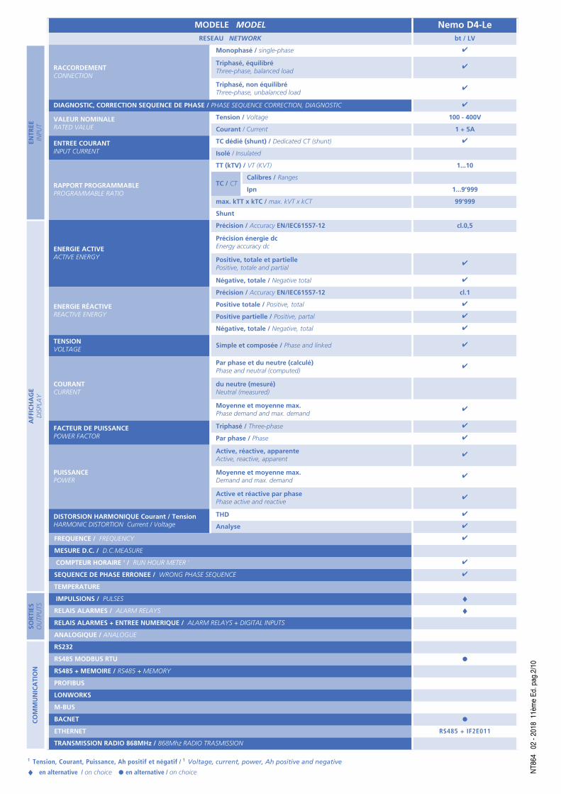
MODELE MODEL Nemo D4-LeRESEAU NETWORK bt / LV
RACCORDEMENTCONNECTION
Monophasé / single-phase ✔
Triphasé, équilibréThree-phase, balanced load
✔
Triphasé, non équilibréThree-phase, unbalanced load
✔
DIAGNOSTIC, CORRECTION SEQUENCE DE PHASE / PHASE SEQUENCE CORRECTION, DIAGNOSTIC ✔
VALEUR NOMINALERATED VALUE
Tension / Voltage 100 - 400V
Courant / Current 1 + 5A
ENTREE COURANTINPUT CURRENT
TC dédié (shunt) / Dedicated CT (shunt) ✔
Isolé / Insulated
RAPPORT PROGRAMMABLEPROGRAMMABLE RATIO
TT (kTV) / VT (KVT) 1...10
TC / CTCalibres / Ranges
Ipn 1...9’999
max. kTT x kTC / max. kVT x kCT 99’999
Shunt
ENERGIE ACTIVEACTIVE ENERGY
Précision / Accuracy EN/IEC61557-12 cl.0,5
Précision énergie dc Energy accuracy dc
Positive, totale et partiellePositive, totale and partial
✔
Négative, totale / Negative total ✔
ENERGIE RÉACTIVEREACTIVE ENERGY
Précision / Accuracy EN/IEC61557-12 cl.1
Positive totale / Positive, total ✔
Positive partielle / Positive, partal ✔
Négative, totale / Negative, total ✔
TENSIONVOLTAGE
Simple et composée / Phase and linked ✔
COURANTCURRENT
Par phase et du neutre (calculé)Phase and neutral (computed)
✔
du neutre (mesuré)Neutral (measured)
Moyenne et moyenne max.Phase demand and max. demand
✔
FACTEUR DE PUISSANCEPOWER FACTOR
Triphasé / Three-phase ✔
Par phase / Phase ✔
PUISSANCEPOWER
Active, réactive, apparenteActive, reactive, apparent
✔
Moyenne et moyenne max.Demand and max. demand
✔
Active et réactive par phasePhase active and reactive
✔
DISTORSION HARMONIQUE Courant / TensionHARMONIC DISTORTION Current / Voltage
THD ✔
Analyse ✔
FREQUENCE / FREQUENCY ✔
MESURE D.C. / D.C.MEASURE
COMPTEUR HORAIRE 1 / RUN HOUR METER 1 ✔
SEQUENCE DE PHASE ERRONEE / WRONG PHASE SEQUENCE ✔
TEMPERATURE
IMPULSIONS / PULSES ♦RELAIS ALARMES / ALARM RELAYS ♦RELAIS ALARMES + ENTREE NUMERIQUE / ALARM RELAYS + DIGITAL INPUTS
ANALOGIQUE / ANALOGUE
RS232
RS485 MODBUS RTU ●RS485 + MEMOIRE / RS485 + MEMORY
PROFIBUS
LONWORKS
M-BUS
BACNET ●ETHERNET RS485 + IF2E011
TRANSMISSION RADIO 868MHz / 868Mhz RADIO TRASMISSION
COMMUNICATION
AFFICHAGE
DISPLAY
SORTIES
OUTPUTS
ENTREE
INPUT
NT86
402
- 201
8 11
ème E
d. pa
g.2/10

LEGENGE : = Paramètres programmables= Reset Parameter
AFFICHAGE
Type d’affichage: cristaux liquides rétroéclairés (LCD)= Rétroéclairage sélectionnable : 0 - 35 - 70 - 100%Réduction automatique du rétroéclairage (de la valeur sélectionnée), temporisation20 secondes d’inactivité du clavierRétroéclairage 100% à la pression sur le clavierPoints d’affichage: 10.000 4 chiffres (hauteur des chiffres 12 mm)Unité de mesure: affichage automatique en fonction des rapports TT et TC sélectionnésRésolution: automatiquePoint décimal: automatiqueMise à jour de la lecture : 1 lecture/sComptage de l’énergie: 8 chiffresL’affichage est divisé en 4 menus accessible à l’aide des touchescorrespondantes :
La page d’affichage change selon la mesure programmée
PARAMETRES PROGRAMMABLES
Programmation: par touches tactiles en façade, 4 touchesAccès à la programmation: protégé par un mot de passeMenu programmation: subdivisé en deux niveauxNIVEAU 1
Page d’affichage personnaliséeRaccordementTemps d’intégration courant/puissance moyenneAffichage rétroéclairageDémarrage du comptage du compteurCommunication RS485Fonction sortie relais impulsions ou alarme ou commutation état
NIVEAU 2Mode de comptage de l’énergieRapport TC et TT externes
MODE DE COMPTAGE DE L’ENERGIE
4 modes sélectionnables : synchrone, asynchrone, tariff, comptage des impulsions
DISPLAY
Type of display: backlighted liquid crystal= Selectable backlighting: 0 - 35 - 70 - 100%Backlighting automatic reduction (to the selected value) after approximately 20seconds of keyboard idle100% backlighting after first pressure on the keyboardReading points: 10.000 4 digits (high digit 12 mm)Engineering unit: automatic display according to the set VT and CT ratiosResolution: automaticDecimal point: automaticDisplay updating : 1 reading/sEnergy count: 8 digitsDisplay is subdivided into 4 menus which are accessible through the relevantfunction keys :
Display page change according to the programmed measuring mode
PROGRAMMABLE PARAMETERS
Programming: through touch-screen front keyboard, 4 keysProgramming access: password-protectedProgramming menu: subdivided on two levelsLEVEL 1
Customized display pageConnectionAverage power/current delay timeDisplay backlightingLapsed time count startRS485 communicationRelay output function pulses or alarm or state switching
LEVEL 2Energy count modeExternal voltage or current transformer ratio
ENERGY COUNT MODE
4 selectable modes synchronous, asynchronous, tariff, pulse counting
REFERENCE ORDERING CODE
SORTIEOUTPUT
ALIM. AUX.AUX. SUPPLY
ENTREEINPUT
9017 6071Impulsions / Alarme / Commutation état
Pulses / alarm / state switching
80...265Vac 100...300Vdc
80...500V 1 et / and 5A
9017 6072Impulsions / Alarme / Commutation état + RS485 ModBus RTU
Pulses / alarm / state switching + RS485 Modbus RTU
9017 6070Impulsions / Alarme / Commutation état + RS485 BACNET
Pulses / alarm / state switching + RS485 BACNET
9017 6074Impulsions / Alarme / Commutation état
Pulses / alarm / state switching
11...60Vdc9017 6075Impulsions / Alarme / Commutation état + RS485 ModBus RTU
Pulses / alarm / state switching + RS485 Modbus RTU
9017 6073Impulsions / Alarme / Commutation état + RS485 BACNET
Pulses / alarm / state switching + RS485 BACNET
NT86
402
- 201
8 11
ème E
d. pa
g.3/10
✘
LEGENGE : = Paramètres programmables= Reset Parameter✘
U � I � P�Q�S
�
E�PF�F OK
Comptage énergie partiellePartial Energy Count
Energie 4 TariffEnergy 4 Tariffs
Comptage impulsionsPulse Counter
SYNCHRONESynchronus
Activé par entrées numériquesActivated by digital inpuls
-- --
ASYNCHRONEAsynchronus
Toujours actifAlways active
-- --
TARIFFTariff -- Commutation tarif avec entrées numériques
Tariff switching with digital inputs--
COMPTAGE IMPULSIONSPulse counting
Toujours actifAlways active
Activé par entrées numériquesActivated by digital inputs
TENSIONpar phase et composée
VOLTAGEphase and linked
COURANTpar phase et du neutre
CURRENTphase and neutral
PUISSANCE TRIPHASEEactive réactive, apparente, déformée
THREE-PHASE POWER active, reactive, apparent, distorting1
FACTEUR DE PUISSANCEpar phase et triphaséPOWER FACTOR
phase and three-phase
TENSION MINIMUMpar phase
MINIMUM VOLTAGEphase
COURANT MOYENpar phase
CURRENT DEMANDphase
PUISSANCE PAR PHASEactive, réactive, apparente
PHASE POWER active, reactive, apparent
ANGLE DE PHASE COURANT TENSIONpar phase et triphasé
PHASE ANGLE CURRENT-VOLTAGEphase and three-phase
TENSION MAXIMUMpar phase
MAXIMUM VOLTAGEphase
COURANT MOYEN MAX.par phase
MAX. CURRENT DEMANDphase
PUISSANCE MOYENNEactive, réactive, apparente
POWER DEMANDactive, reactive, apparent
FREQUENCEFREQUENCY
DISTORSION HARMONIQUE TENSIONpar phase et composée
VOLTAGE HARMONIC DISTORTIONphase or linked
MOYENNE DES 3 COURANTSAVERAGE CURRENT
I1 + I2 + I33
PUISSANCE MOYEN. MAX.active, réactive, apparente
MAX. POWER DEMANDactive, reactive, apparent
COMPTEUR HORAIRERUN HOUR METER
ANALYSE HARMONIQUES2
par phase et composéeH03/05/07/09
HARMONIC ANALYSIS2
phase or linked
DISTORSION HARMONIQUE COURANTpar phase
CURRENT HARMONIC DISTORTIONphase
ENERGIE ACTIVE TOTALEpositive et négative
TOTAL ACTIVE ENERGYpositive and negative
FACTEUR DE CRETECREST FACTOR
ANALYSE HARMONIQUE2
par phaseH03/05/07/09
HARMONIC ANALYSIS2
phase
ENERGIE REACTIVE TOTALEpositive et négative
TOTALE REACTIVE ENERGYpositive and negative
ANGLE DE PHASE entre tensions
PHASE ANGLE between voltages
FACTEUR DE CRETECREST FACTOR
ENERGIE ACTIVE PARTIELLEpositive et négative
PARTIAL ACTIVE ENERGYpositive and negative
ANGLE DE PHASE entre courants
PHASE ANGLE between currents
ENERGIE REACTIVE PARTIELLEpositive et négative
PARTIAL REACTIVE ENERGYpositive and negative
COMPTAGE IMPULSIONSEtat de l’entrée Impulsion
PULSE METERINGState of Pulse Input
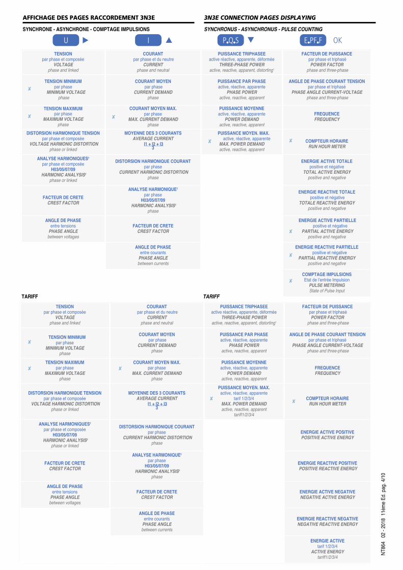
3N3E CONNECTION PAGES DISPLAYING
SYNCHRONUS - ASYNCHRONUS - PULSE COUNTING
AFFICHAGE DES PAGES RACCORDEMENT 3N3E
SYNCHRONE - ASYNCHRONE - COMPTAGE IMPULSIONS
TENSIONpar phase et composée
VOLTAGEphase and linked
COURANTpar phase et du neutre
CURRENTphase and neutral
PUISSANCE TRIPHASEEactive réactive, apparente, déformée
THREE-PHASE POWER active, reactive, apparent, distorting1
FACTEUR DE PUISSANCEpar phase et triphaséPOWER FACTOR
phase and three-phase
TENSION MINIMUMpar phase
MINIMUM VOLTAGEphase
COURANT MOYENpar phase
CURRENT DEMANDphase
PUISSANCE PAR PHASEactive, réactive, apparente
PHASE POWER active, reactive, apparent
ANGLE DE PHASE COURANT TENSIONpar phase et triphasé
PHASE ANGLE CURRENT-VOLTAGEphase and three-phase
TENSION MAXIMUMpar phase
MAXIMUM VOLTAGEphase
COURANT MOYEN MAX.par phase
MAX. CURRENT DEMANDphase
PUISSANCE MOYENNEactive, réactive, apparente
POWER DEMANDactive, reactive, apparent
FREQUENCEFREQUENCY
DISTORSION HARMONIQUE TENSIONpar phase et composée
VOLTAGE HARMONIC DISTORTIONphase or linked
MOYENNE DES 3 COURANTSAVERAGE CURRENT
I1 + I2 + I33
PUISSANCE MOYEN. MAX.active, réactive, apparente
tarif 1/2/3/4MAX. POWER DEMANDactive, reactive, apparent
tariff1/2/3/4
COMPTEUR HORAIRERUN HOUR METER
ANALYSE HARMONIQUES2
par phase et composéeH03/05/07/09
HARMONIC ANALYSIS2
phase or linked
DISTORSION HARMONIQUE COURANTpar phase
CURRENT HARMONIC DISTORTIONphase
ENERGIE ACTIVE POSITIVEPOSITIVE ACTIVE ENERGY
FACTEUR DE CRETECREST FACTOR
ANALYSE HARMONIQUE2
par phaseH03/05/07/09
HARMONIC ANALYSIS2
phase
ENERGIE REACTIVE POSITIVEPOSITIVE REACTIVE ENERGY
ANGLE DE PHASE entre tensions
PHASE ANGLE between voltages
FACTEUR DE CRETECREST FACTOR
ENERGIE ACTIVE NEGATIVENEGATIVE ACTIVE ENERGY
ANGLE DE PHASE entre courants
PHASE ANGLE between currents
ENERGIE REACTIVE NEGATIVENEGATIVE REACTIVE ENERGY
ENERGIE ACTIVE tarif 1/2/3/4
ACTIVE ENERGYtariff1/2/3/4
TARIFFTARIFF
U � I � P�Q�S
�
E�PF�F OK
✘
✘ ✘
✘ ✘
✘
✘
✘
✘
✘ ✘
✘✘
NT86
402
- 201
8 11
ème E
d. pa
g. 4/1
0

DISTORSION PUISSANCE1Dans les systèmes triphasés, la relation entre P,Q et S est normalement lasuivante :S = V x I = √ P2 + Q2
Ceci s'applique en l'absence de distorsion d’harmonique.S’il existe des distorsions du courant, le rapport doit être corrigé comme suit:S = V x I = √ P2 + Q2 + D2
où D signifie puissance “déformée”.ANALYSE HARMONIQUES2Le calcul du contenu d’harmoniques du signal d’entrée tient compte de la présenceéventuelle des inter-harmoniques, qui généralement sont présentes lorsque laforme d’onde est cycliquement interrompue.Dans ces cas, il n'y a pas d'harmoniques à des fréquences multiples de lafréquence fondamentale, mais au milieu de deux valeurs consécutives :ex.: 50Hz (fondamentale)inter-harmoniques: 87,5Hz (50-100Hz) ou 112,5Hz (100-150Hz) Afin de présenter les données d'une manière standard, le contenu d’harmonique,comme dans l’exemple, est attribué correctement à l’harmonique centrale la plusproche dans la plage 50...100Hz qui est 100Hz (seconde harmonique).
Mise à jour mesure : 5 lectures/sec
ENTREE
Réseau : monophasé, triphasé 3 et fils
Raccordement sur transformateur de courant externe dédiéTension triphasée nominale Un: 400-100V (phase-phase)Tension triphasée: 80...500V (phase-phase)Tension monophasée: 50 - 290VRapport TT externe : 1...10,0 (tension primaire max. TT 1200V)In Courant nominal: 5A - 1ASurcharge instantanée: 20 In/0,5 secondesRapport TC externe : 1...9999 (courant primaire max. 50kA/5A - 10kA/1A)Fn Fréquence nominale: 50Hz - 400Hz (sélection automatique)Variation admissible: 45...65Hz (fn 50Hz) - 360...440Hz (fn 400Hz)Type de mesure: valeur efficace vraieContenu des harmoniques: jusqu’au rang 50 (45...65Hz)
DISTORTING POWER 1In normal 3-phase systems, usually the relationship between P,Q and S is as in thefollowing:S = V x I = √ P2 + Q2
This is true when no distortionis present in the currents. When the currents havesome way a harmonic contents, yhe formula must be corrected in this way:S = V x I = √ P2 + Q2 + D2
where D has the meaning “deforming” power.HARMONIC ANALYSE2The calculation of the harmonic contents of the incoming signal keeps in accountthe possible presence of inter-harmonics that normally is found when the waveformis cyclically interrupted (burst fired).In these cases, there aren’t any harmonics at frequencies multiple of thefundamental but in the ranges between two consecutive values:eg.: 50Hz (fundamental)inter-harmonics: 87,5Hz (50-100Hz) or 112,5Hz (100-150Hz)To show the results in a standard way, the harmonic contents, as in the example,are correctly attributed to the nearest central harmonic in the range 50...150Hz thatis 100Hz (second harmonic).
Measuring updateing : 5 reading/sec
INPUT
Network : single phase, three-phase network 3 and 4-wire
Connection with external dedicated current transformersThree-phase voltage rating Un: 400-100V (phase-phase)Three-phase voltage: 80...500V (phase-phase)Single-phase voltage: 50 - 290VExternal VT ratio : 1...10,0 (max. VT primary voltage 1200V)In rated current : 5A - 1AInstantaneous overload: 20In/0,5 secondsExternal CT ratio : 1...9999 (max. primary current 50kA/5A - 10kA/1A)Fn Rated frequency : 50Hz - 400Hz (automatic selection)Admitted variation: 45...65Hz (fn 50Hz) - 360...440Hz (fn 400Hz)Type of measurement: true root mean squareHarmonic content: up to 50th harmonic (45...65Hz)
NT86
402
- 201
8 11
ème E
d. pa
g.5/10
PRÉCISION EN CONFORMITE AVEC’ CONFORMITY ACCURACY WITH EN/IEC 61557-12Energie active Active energy Ea cl.0,5Energie réactive Reactive energy Erv cl.1Tension Voltage U cl.0,5Courant Current I cl.0,5Puissance active Active power P cl.0,5Puissance réactive Reactive power Qv cl.1Puissance apparente Apparent power Sv cl.1Fréquence Frequence f ± 0,1HzTHD (jusqu’au rang 50) THD (up to 50th harmonic)Harmonique simple Harmonics single THDu / THDi cl.1
SymboleSymbol
RéseauNetwork
ChargeLoad
N° TC externeExternal CT number
SchémaDiagram
RaccordementConnection
1N1E MonophaséSingle-phase -- 1 S.1000/410 --
3-1E Triphasé 3 fils3-phase 3 wires
EquilibréBalance 1 S.1000/411 --
3N1E Triphasé 4 fils3-phase 4 wires
EquilibréBalance 1 S.1000/412 --
3-2E Triphasé 3 fils3-phase 3 wires
Non équilibréUnbalance 2 S.1000/413 Aron L1-L3
3-3E Triphasé 3 fils3-phase 3 wires
Non équilibréUnbalance 3
S.1000/414 --
S.1000/416 Raccordement TC avec point commun, 1 retourCT connection with common point, 1 return
3N3E Triphasé 3 fils3-phase 3 wires
Non équilibréUnbalance 3
S.1000/415 --
S.1000/417 Raccordement TC avec point commun, 1 retourCT connection with common point, 1 return
NT86
402
- 201
8 11
ème E
d. pa
g.6/10
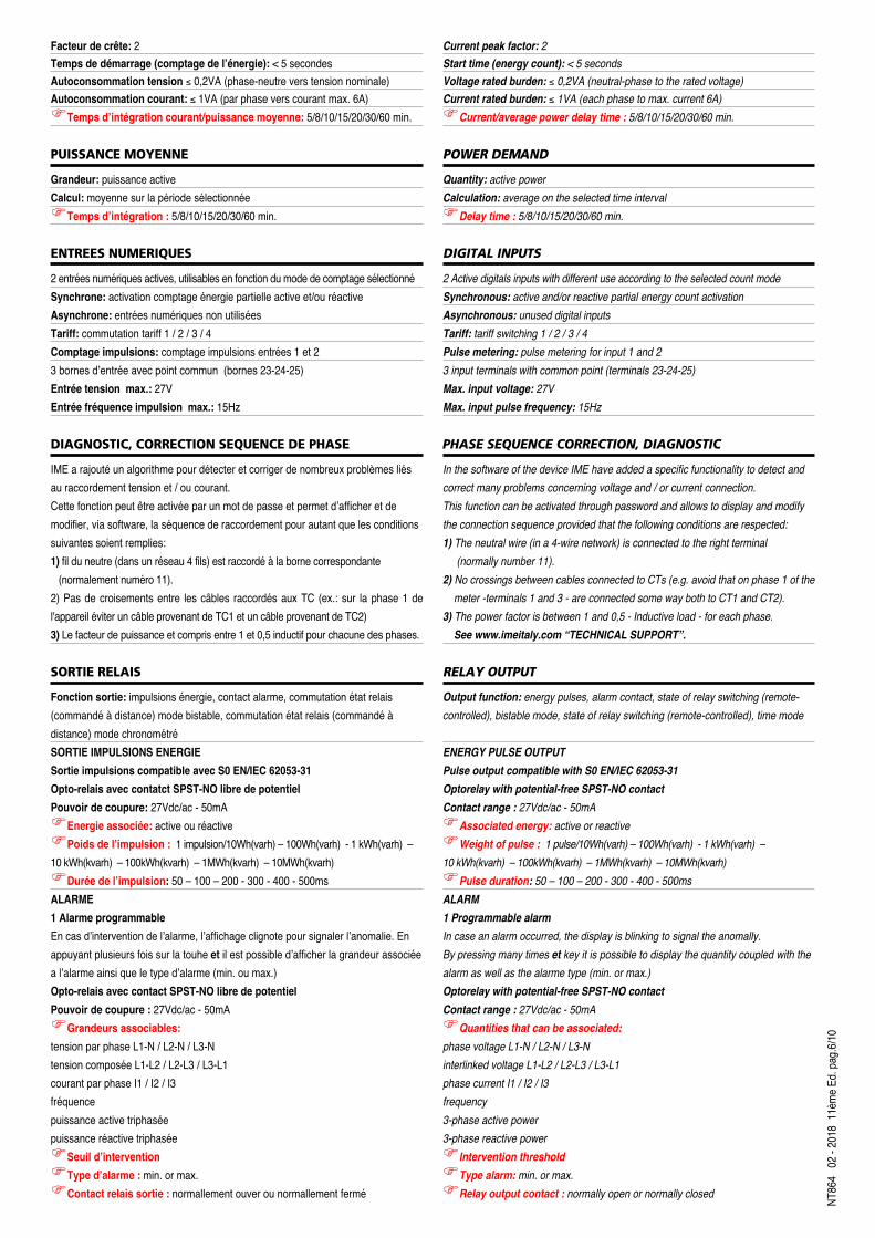
Facteur de crête: 2 Temps de démarrage (comptage de l’énergie): < 5 secondesAutoconsommation tension ≤ 0,2VA (phase-neutre vers tension nominale)Autoconsommation courant: ≤ 1VA (par phase vers courant max. 6A)Temps d’intégration courant/puissance moyenne: 5/8/10/15/20/30/60 min.
PUISSANCE MOYENNE
Grandeur: puissance activeCalcul: moyenne sur la période sélectionnéeTemps d’intégration : 5/8/10/15/20/30/60 min.
ENTREES NUMERIQUES
2 entrées numériques actives, utilisables en fonction du mode de comptage sélectionnéSynchrone: activation comptage énergie partielle active et/ou réactiveAsynchrone: entrées numériques non utiliséesTariff: commutation tariff 1 / 2 / 3 / 4Comptage impulsions: comptage impulsions entrées 1 et 23 bornes d’entrée avec point commun (bornes 23-24-25)Entrée tension max.: 27VEntrée fréquence impulsion max.: 15Hz
DIAGNOSTIC, CORRECTION SEQUENCE DE PHASE
IME a rajouté un algorithme pour détecter et corriger de nombreux problèmes liésau raccordement tension et / ou courant.Cette fonction peut être activée par un mot de passe et permet d’afficher et demodifier, via software, la séquence de raccordement pour autant que les conditionssuivantes soient remplies:1) fil du neutre (dans un réseau 4 fils) est raccordé à la borne correspondante
(normalement numéro 11).2) Pas de croisements entre les câbles raccordés aux TC (ex.: sur la phase 1 del'appareil éviter un câble provenant de TC1 et un câble provenant de TC2)3) Le facteur de puissance et compris entre 1 et 0,5 inductif pour chacune des phases.
SORTIE RELAIS
Fonction sortie: impulsions énergie, contact alarme, commutation état relais(commandé à distance) mode bistable, commutation état relais (commandé àdistance) mode chronométréSORTIE IMPULSIONS ENERGIESortie impulsions compatible avec S0 EN/IEC 62053-31Opto-relais avec contatct SPST-NO libre de potentielPouvoir de coupure: 27Vdc/ac - 50mAEnergie associée: active ou réactivePoids de l’impulsion : 1 impulsion/10Wh(varh) – 100Wh(varh) - 1 kWh(varh) – 10 kWh(kvarh) – 100kWh(kvarh) – 1MWh(kvarh) – 10MWh(kvarh) Durée de l’impulsion: 50 – 100 – 200 - 300 - 400 - 500msALARME1 Alarme programmableEn cas d’intervention de l’alarme, l’affichage clignote pour signaler l’anomalie. Enappuyant plusieurs fois sur la touhe et il est possible d’afficher la grandeur associéea l’alarme ainsi que le type d’alarme (min. ou max.)Opto-relais avec contact SPST-NO libre de potentielPouvoir de coupure : 27Vdc/ac - 50mAGrandeurs associables: tension par phase L1-N / L2-N / L3-Ntension composée L1-L2 / L2-L3 / L3-L1courant par phase I1 / I2 / I3fréquencepuissance active triphaséepuissance réactive triphaséeSeuil d’interventionType d’alarme : min. or max.Contact relais sortie : normallement ouver ou normallement fermé
Current peak factor: 2Start time (energy count): < 5 secondsVoltage rated burden: ≤ 0,2VA (neutral-phase to the rated voltage)Current rated burden: ≤ 1VA (each phase to max. current 6A)Current/average power delay time : 5/8/10/15/20/30/60 min.
POWER DEMAND
Quantity: active powerCalculation: average on the selected time intervalDelay time : 5/8/10/15/20/30/60 min.
DIGITAL INPUTS
2 Active digitals inputs with different use according to the selected count modeSynchronous: active and/or reactive partial energy count activationAsynchronous: unused digital inputsTariff: tariff switching 1 / 2 / 3 / 4Pulse metering: pulse metering for input 1 and 23 input terminals with common point (terminals 23-24-25)Max. input voltage: 27VMax. input pulse frequency: 15Hz
PHASE SEQUENCE CORRECTION, DIAGNOSTIC
In the software of the device IME have added a specific functionality to detect andcorrect many problems concerning voltage and / or current connection.This function can be activated through password and allows to display and modifythe connection sequence provided that the following conditions are respected:1) The neutral wire (in a 4-wire network) is connected to the right terminal
(normally number 11).2) No crossings between cables connected to CTs (e.g. avoid that on phase 1 of the
meter -terminals 1 and 3 - are connected some way both to CT1 and CT2).3) The power factor is between 1 and 0,5 - Inductive load - for each phase.
See www.imeitaly.com “TECHNICAL SUPPORT”.
RELAY OUTPUT
Output function: energy pulses, alarm contact, state of relay switching (remote-controlled), bistable mode, state of relay switching (remote-controlled), time mode
ENERGY PULSE OUTPUTPulse output compatible with S0 EN/IEC 62053-31Optorelay with potential-free SPST-NO contactContact range : 27Vdc/ac - 50mAAssociated energy: active or reactiveWeight of pulse : 1 pulse/10Wh(varh) – 100Wh(varh) - 1 kWh(varh) – 10 kWh(kvarh) – 100kWh(kvarh) – 1MWh(kvarh) – 10MWh(kvarh) Pulse duration: 50 – 100 – 200 - 300 - 400 - 500msALARM1 Programmable alarmIn case an alarm occurred, the display is blinking to signal the anomally.By pressing many times et key it is possible to display the quantity coupled with thealarm as well as the alarme type (min. or max.)Optorelay with potential-free SPST-NO contactContact range : 27Vdc/ac - 50mAQuantities that can be associated: phase voltage L1-N / L2-N / L3-Ninterlinked voltage L1-L2 / L2-L3 / L3-L1phase current I1 / I2 / I3frequency3-phase active power3-phase reactive powerIntervention thresholdType alarm: min. or max.Relay output contact : normally open or normally closed

Hystérésis : 0-20%Délai d’intervention : 0,99sDélai de réarmemement : 0,99sEtat commutation relais (commandé à distance), mode bistableContact sortie relais: normallement ouvert (no) ou normallement fermé (nC)t on: délai entre l’activation à distance et changement d’état du relaist oF : délai entre le reset à distance et le changement de statut du relaisValeur sélectionnabes t on / t oF : 0,99sEtat commutation relais (commandé à distance), mode chronométréContact sortie relais: normallement ouvert (no) ou normallement fermé (nC)t on: délai entre l’activation à distance et changement d’état du relaist oF : délai entre le changement d’état du relais (activation) et le resetValeur sélectionnabes t on / t oF : 0,99s
COMMUNICATION RS485 Modbus
Isolée galvaniquement de l’entrée et de l’alimentation auxiliaireStandard: RS485 - 3 filsTransmission: asynchrone sérieProtocole: Modbus RTU - Modbus TCP (reconnaissance automatique)Nombre d’adresse : 1...255Nombre de bits: 8Bit de stop: 1Bit de parité: sans - paire - impairTemps de réponse à l’interrogation: 3...100msVitesse de transmission : 4’800 - 9’600 - 19’200 - 38’400 bit/secondMessage Modbus format Word: Big Endian, Little Endian, SwapExemple :Message demande: 01 03 10 00 00 02 CO CBRéponse:Big Endian = 01 03 04 01 02 03 04 CB XX YYLittle Endian = 01 03 04 04 03 02 01 CB XX YYSwap = 01 03 04 03 04 01 02 CB XX YYNbre max. d’appareils raccordés au réseau: 32 (jusqu’à 255 avec répétiteur RS485)Distance max. du superviseur: 1200m
COMMUNICATION RS485 BACNET
Isolée galvaniquement de l’entrée et de l’alimentation auxiliaireStandard: RS485 - 3 filsTransmission: asynchrone sérieProtocole: BACNET MS-TPNombre d’adresse : 0...127Vitesse de transmission : 9’600 - 19’200 - 38’400 - 76’800 bit/sNombre de bits: 8Bit de stop: 1Bit de parité: sans - pair - impairAdresses réseau: 0...4000Nbre max. d’appareils raccordés au réseau: 32 (jusqu’à 255 avec répétiteur RS485)Distance max. du superviseur: 1200m
COMMUNICATION ETHERNET (NT809 - NT891)
Réalisable avec les interfaces IF2E ou IF4E (RS485/Ethernet)
ISOLEMENT (EN/IEC 61010-1)
Catégorie de l’installation: IIIDegré de pollution: 2Tension de référence pour l’isolement: 300V (Phase - neutre)
COMPATIBILITE ELECTROMAGNETIQUE
Emission selon EN / IEC 61326-1 classe BImmunité selon EN / IEC 61326-1
Hystérésis : 0-20%Intervention delay : 0,99sReset delay : 0,99sState of relay switching (remote-controlled), bistable modeRelay output contact: normally open (no) or normally closed (nC)t on: delay between activation remote control and change of state of relayt oF : delay between reset remote control and change of state of relaySelectable values to on / t oF : 0,99sState of relay switching (remote-controlled), time modeRelay output contact: normally open (no) or normally closed (nC)t on: delay between activation remote control and change of state of relayt oF : delay between change of state of relay (activation) and resetSelectable values to on / t oF : 0,99s
RS485 Modbus COMMUNICATION
Galvanically insulated from input and auxiliairy supplyStandard: RS485 - 3 wiresTransmission: serial asynchronousProtocol: Modbus RTU - Modbus TCP (autorecognition)Number of address : 1...255Number of bits: 8Stop bit: 1Parity bit: none - even - oddAnswer waiting time: 3...100msTransmission speed : 4’800 - 9’600 - 19’200 - 38’400 bit/secondModbus word message format: Big Endian, Little Endian, SwapExample :Request message: 01 03 10 00 00 02 CO CBAnswer:Big Endian = 01 03 04 01 02 03 04 CB XX YYLittle Endian = 01 03 04 04 03 02 01 CB XX YYSwap = 01 03 04 03 04 01 02 CB XX YYMax. number of devices that can be network-connected: 32 (up to 255 with RS485 repeator)
Max. distance from the supervisor: 1200m
BACNET RS485 COMMUNICATION
Galvanically insulated from input and auxiliary supplyStandard: RS485 - 3 wiresTransmission: serial asynchronousProtocol: BACNET MS-TPNumber of address : 0...127Transmission speed : 9’600 - 19’200 - 38’400 - 76’800 bit/sNumber of bits: 8Stop bit: 1Parity bit: none - even - oddNetwork address: 0...4000Max. number of devices that can be network-connected: 32 (up to 255 with RS485 repeator)
Max. distance from the supervisor: 1200m
ETHERNET COMMUNICATION (NT809 - NT891)
It can be carried out with models IF2E or IF4E (RS485/Ethernet) interface
INSULATION (EN/IEC 61010-1)
Installation category: IIIPollution degree: 2Insulation voltage rating: 300V (phase - neutral)
ELETROMAGNETIC COMPATIBILITY
Emission according to EN 61326-1 class B Immunity according to EN 61326-1
NT86
402
- 201
8 11
ème E
d. pa
g.7/10
ALIMENTATION AUXILIAIRE
Valeur nominale Uaux ca: 80...265Vac - 48Vac Fréquence nominale fn: 50 ou 400Hz (sélection automatique)Fréquence de fonctionnement: 45…65Hz (fn 50Hz) ou 360...440Hz (fn 400Hz)Autoconsommation: ≤ 2,5VA (230Vca backlight 30%)Valeur nominale Uaux cc: 100...300Vdc - 20...60VdcAutoconsommation: ≤ 2,5W (24Vdc backlight 30%)Protection contre l’inversion de polarité
CONDITIONS D’UTILISATION
Température de référence: 23°C ± 2°CTempérature de fonctionnement spécifique: -5...55°CTempérature limite pour le stockage et le transport: - 25...70°CAdapté pour l’utilisation en milieu tropicalPuissance max. dissipée1: ≤ 5W1Pour le dimensionnement thermique du coffret
BOITIER
Boîtier : 4 modules DIN 43880Montage: rail 35mmType de profil: TH35-15 (EN60715)Matériau du boîtier: polycarbonate autoextinguibleDegré de protection (EN60529): IP54 face avant, IP20 bornesPoids: 250 grammes
CAPACITE DES BORNES
ENTREE TENSIONALIMENTATION AUXILIAIRESORTIEAvec embout: min.0,05mm2 / max. 4mm2
Fil souple: min.0,05mm2 / max. 2,5mm2
Couple de serrage max: 0,6NmENTREE COURANTAvec embout : min.0,05mm2 / max. 6mm2
Fil souple: min.0,05mm2 / max. 4mm2
AUXILIARY SUPPLY
Rated value Uaux ac: 80...265Vac - 48Vac Rated frequency fn: 50 or 400Hz (automatic selection)Working frequency: 45…65Hz (fn 50Hz) or 360...440Hz (fn 400Hz)Rated burden: ≤ 2,5VA (230Vac backlight 30%)Rated value Uaux dc: 100...300Vdc - 20...60VdcRated burden: ≤ 2,5W (24Vdc backlight 30%)Protected against incorrect polarity
ENVIRONMENTAL CONDITIONS
Reference temperature: 23°C ± 2°CSpecified operating range: -5...55°CLimit range for storage and transport: - 25...70°CSuitable for tropical climatesMax. power dissipation 1: ≤ 5W1For switchboard thermal calculation
HOUSING
Housing: 4 moduli DIN 43880Mounting: snap-on 35mm rail Rail type: top hat TH35-15 (EN60715)Housing material: self-extinguishing policarbonateProtection degree (EN60529): IP54 front frame, IP20 terminalsWeight: 250 grams
TERMINAL CAPACITY
VOLTAGE INPUTAUX. SUPPLYOUTPUTWith lag: min.0,05mm2 / max. 4mm2
Flexible cable: min.0,05mm2 / max. 2,5mm2
Tightening torque advised: 0,6NmCURRENT INPUTWith lag: min.0,05mm2 / max. 6mm2
Flexible cable: min.0,05mm2 / max. 4mm2
Tightening torque advised: 1Nm
NT86
402
- 201
8 11
ème E
d. pa
g.8/10
TESTS TESTS
Circuits considérés Considered circuits Tension à impulsions 1,2 / 50μs 0,5J
Voltage test 1,2 / 50μs 0,5J
Tension alternative valeur efficace 50Hz 1min
Alternating voltage r.m.s value 50Hz 1min
Alimentation / Entrées voltmétriques Supply / Voltmetric inputs 6kV 3kVEntrées mesure / Communication RS485Measure inputs / RS485Communication 6kV 3kV
Entrées mesure / Sorties impulsions Meaure inputs / Pulse output 6kV 3kVTous les circuits et la masse All circuits and earth 4kV
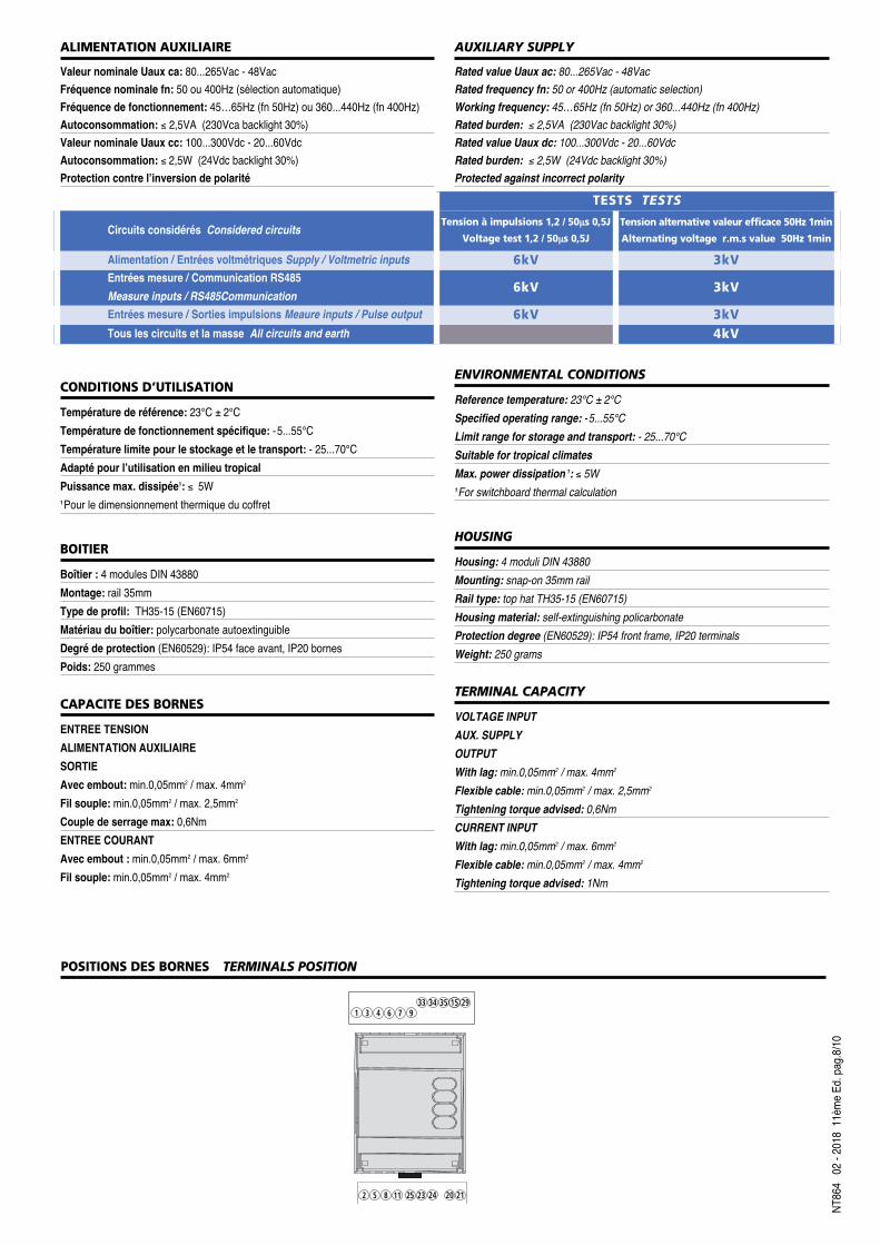
POSITIONS DES BORNES TERMINALS POSITION
6 71 3 435 15
933 34
20 212 5 8
29
11 25 23 24

NT86
402
- 201
8 11
ème E
d. pa
g.9/10
SCHEMA DE RACCORDEMENT WIRING DIAGRAMS
2 5 8 111 3 6 94 7
S1
P1
a
A
b
BL
N LOADX
2 11
INPUT
VOLTAGE CURRENT
15 29 20
AUX.SUPPLY
21+ –
33 34 35
RS 485
Rx / Tx GND + E1 E2 –
F
25 23 24
DIGITAL INPUT
C
X
XX
S1
P1
a
AL1
L2
L3
NX X X
LOAD
INPUT
VOLTAGE CURRENT
2 5 8 1 3 64 711
2 5 8 11
9 15 29 33 34 35
RS 485
Rx / Tx GND + E1 E2 –
25 23 24
DIGITAL INPUT
C
20
AUX.SUPPLY
21+ –
F
X
XX
S1
P1
a
A
b
B
a
A
b
BL1
L2
L3
LOAD
2 5 8
INPUT
VOLTAGE CURRENT
2 5 8 1 3 6 94 711 15 29 33 34 35
RS 485
Rx / Tx GND + E1 E2 –
25 23 24
DIGITAL INPUT
C20
AUX.SUPPLY
21+ –
F
X
XX
S1
P1
S1
P1
a
A
b
B
a
A
b
BL1
L2
L3
LOAD
2 5 8
INPUT
VOLTAGE CURRENT
2 5 8 1 3 6 94 711 15 29 33 34 35
RS 485
Rx / Tx GND + E1 E2 –
25 23 24
DIGITAL INPUT
C
20
AUX.SUPPLY
21+ –
F
S 1000/413
S 1000/412
S 1000/411
S 1000/410
3-1ERéseau triphasé 3 fils 1 système
Three-phase 3-wires network 1 System
3N1ERéseau triphasé 4 fils 1 système
Three-phase 4-wires network, 1 System
3-2ERéseau triphasé 3 fils 2 systèmes
Three-phase 3-wires network, 2 Systems
X
XX
S1
P1 S1
P1 S1
P1
a
A
b
B
a
A
b
BL1
L2
L3
LOAD
2 5 8
INPUT
VOLTAGE CURRENT
2 5 8 1 3 6 94 711 15 29 33 34 35
RS 485
Rx / Tx GND + E1 E2 –
25 23 24
DIGITAL INPUT
C
20
AUX.SUPPLY
21+ –
F
S 1000/414
3-3ERéseau triphasé 3 fils 3 systèmes
Three-phase 3-wires network, 3 System
1n1ERéseau monophaséSingle phase network
F : 0,5A gG

X
XX
S1
P1 S1
P1 S1
P1
a
A
b
B
a
A
b
BL1
L2
L3
LOAD
2 5 8
INPUT
VOLTAGE CURRENT
2 5 8 1 3 6 94 711 15 29 33 34 35
RS 485
Rx / Tx GND + E1 E2 –
25 23 24
DIGITAL INPUT
C
20
AUX.SUPPLY
21+ –
F
X
XX
S1
P1 S1
P1 S1
P1
a
AL1
L2
L3
NX X X
LOAD
INPUT
VOLTAGE CURRENT
2 5 8 1 3 6 94 711
2 5 118
15 29 33 34 35
RS 485
Rx / Tx GND + E1 E2 –
25 23 24
DIGITAL INPUT
C
20
AUX.SUPPLY
21+ –
F
X
XX
S1
P1 S1
P1 S1
P1
a
AL1
L2
L3
NX X X
LOAD
INPUT
VOLTAGE CURRENT
2 5 8 1 3 6 94 711
2 5 8 11
15 29 33 34 35
RS 485
Rx / Tx GND + E1 E2 –
25 23 24
DIGITAL INPUT
C
20
AUX.SUPPLY
21+ –
F
DIMENSIONS DIMENSIONS
3N3ERéseau triphasé 4 fils 3 systèmes
Three-phase 4-wire network, 3 Systems
S 1000/416
3N3ERéseau triphasé 4 fils 3 systèmes
Three-phase 4-wire network, 3 Systems
S 1000/417
3-3ERéseau triphasé 3 fils 3 systèmes
Three-phase 3-wires network, 3 Systems
www.imesys.fr71,2
90
65
44,5
44
S 1000/415
ATTENTION !
The earth connections shown in the wiring diagrams (higlighted in red) arecompulsory. Aux. supply must be connected to terminals 20 and 21.
ATTENTION !
Les raccordements à la terre indiqués sur les schémas de raccordement (misen évidence en rouge) sont obligatoires. L’alimentation auxiliaire doit êtreraccordée aux bornes 20 et 21.
NT86
4 07
- 201
6 9e
Ed.
pag
.10/10
IMES
YS se
rése
rve à
chaq
ue m
omen
t de m
odifie
r les c
aracté
ristiq
ues s
ans p
réavis
écrit
/ IMES
YS re
serve
s the
right
to mo
dify t
he te
chnic
al ch
aracte
ristic
s wi
thout
notic
e.